Here is the final tutorial of this long series. We’re going to see how to apply a texture to a mesh by using mapping coordinates exported from Blender. If you’ve managed to understand the previous tutorials, it will just be some piece of cake to apply some textures. The main concept is once again to interpolate some data between each vertex. In the second part of this tutorial, we’ll see how to boost the performance of our rendering algorithm. For that, we’re going to only display visible faces by using a back-face culling approach. But to go even further, we will use our last secret weapon: the GPU. You will then understand why OpenGL/WebGL and DirectX technologies are so important to make realtime 3D games. They help to use the GPU instead of the CPU to render our 3D objects. To really see the differences, we will load the exact same JSON file inside a WebGL 3D engine named Babylon.JS. The rendering will be far better and the FPS will be without any comparison, especially on low-end devices!
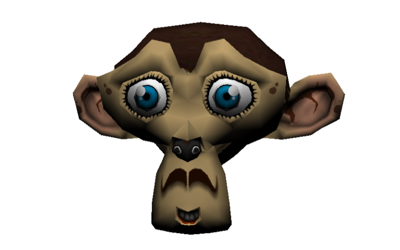
At the end of this tutorial, you will have this final rendering inside our CPU-based 3D software engine:
As a reminder, this tutorial is part of the following series:
1 – Writing the core logic for camera, mesh & device object
2 – Drawing lines and triangles to obtain a wireframe rendering
3 – Loading meshes exported from Blender in a JSON format
4 – Filling the triangle with rasterization and using a Z-Buffer
4b – Bonus: using tips & parallelism to boost the performance
5 – Handling light with Flat Shading & Gouraud Shading
6 – Applying textures, back-face culling and WebGL (this article)
Going further: with David Catuhe, we’ve made a free 8 modules course to let you learn the basics of 3D, WebGL and Babylon.js. The first module is containing a 40 min video version of this tutorial series : Introduction to WebGL 3D with HTML5 and Babylon.js . You’ll learn a lot about WebGL and how to make games using 3D in the browser! Check it out. It’s free & fun.

Texture mapping
Concept
Let’s start by the Wikipedia definition: Texture mapping : “A texture map is applied (mapped) to the surface of a shape or polygon. This process is akin to applying patterned paper to a plain white box. Every vertex in a polygon is assigned a texture coordinate (which in the 2d case is also known as a UV coordinate) either via explicit assignment or by procedural definition. Image sampling locations are then interpolated across the face of a polygon to produce a visual result that seems to have more richness than could otherwise be achieved with a limited number of polygons.”
Let’s now try to understand what this means exactly.
The first time I’ve tried to imagine how we could apply a texture to a 3D mesh was by first thinking about a cube, the first mesh we’ve drawn in this series. I was then thinking about taking an image acting as our texture and map it to each cube’s faces. This could work well in such a simple case. But the first problem will be: what if I’d like to apply a different image/texture on each cube’s faces? A first idea could be to take 6 different images for the 6 sides of your cube. To be even more precise, take 6 images, split them into 2 triangles that will be mapped to the 12 triangles of a cube.
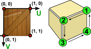
But there is a simpler more elegant approach you’ve probably already played with when you were a child. This image will help you:

The very same approach works perfectly well with 3D engine. Imagine this image as the texture that will be applied to our cube. View it as 2 dimensional array of color’s bytes. We will be able to affect some 2D coordinates moving into this array to each cube’s vertex in order to obtain something like that:

Image taken from this forum thread: Texturing a cube in Blender, and going to pull my hair out
These 2D texture coordinates are known as UV coordinates.
Note: I’ve asked to a 3D guru what were the reasons to name them U & V? The answer was amazingly obvious: “Well, it’s because it’s just before X, Y, Z.”. I was expecting a more complex answer! 😉
You’re now probably asking to yourself how to handle advanced complex meshes like Suzanne, our beautiful monkey’s head, aren’t you?
For this kind of mesh, we’re also going to use a single 2D image that will be mapped in 3D. To build the corresponding texture, we need a planned 2D view of your mesh. This operation is known as an unwrap operation. If you’re a poor developer like myself, trust me, you’ll need a brilliant 3D designer like my friend Michel Rousseau to help you in this phase! And this is exactly what I’ve done: asking for help. 🙂
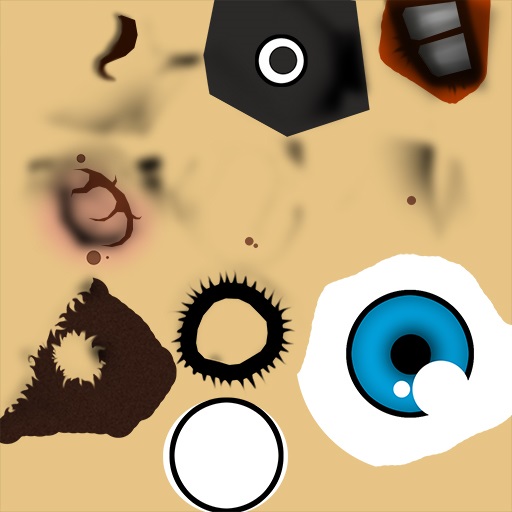
Using the Suzanne model as an example, after the unwrap operation, the designer will obtain this kind of result:

The designer will then paint this planned 2D view and the result will be the texture ready to be used by our engine. In our case, Michel Rousseau has done this job for us and here is his own version of Suzanne:

I know this result may looks weird the first time you try to understand texture mapping. But you should already see something that looks like an eye in the bottom right of the texture. This part will be mapped in 3D to both Suzanne’s eyes using a simple symmetrical operation to differentiate both eyes.
You now known the basics of texture’s mapping. To definitely understand how it works, please read these additional resources I’ve found for you on the web:
– Tutorial 16 – Basic Texture Mapping, read the first part that will help to understand how to map the UV coordinates (living between 0 and 1) to the triangles of our meshes
– Blender 2.6 Manual – UV Mapping a Mesh, that describes the various mapping types
– Tutorial 5 – Texture mapping, read the first part that will definitely help you to at least know how to map a cube. 🙂
Code
We’re now ready to dig into the code. There are several tasks to be done :
1 – Create a Texture class that will load the image acting as the texture and return the color associated to the U & V coordinates interpolated per pixel
2 – Add/Pass the Texture information in the complete rendering flow
3 – Parse the JSON file exported by the Babylon Blender’s Add-on to load the UV coordinates
The Texture logic
In HTML5 with TypeScript/JavaScript, we’re going of course to loading the texture by dynamically creating a canvas element and getting it’s associated image data to obtain our color bytes array.
With C#/XAML, we’re going to create a WriteableBitmap, set its source with the image we will load and get its PixelBuffer property to obtain our color bytes array.
public class Texture
{
    private byte[] internalBuffer;
    private int width;
    private int height;

    // Working with a fix sized texture (512x512, 1024x1024, etc.).
    public Texture(string filename, int width, int height)
    {
        this.width = width;
        this.height = height;
        Load(filename);
    }

    async void Load(string filename)
    {
        var file = await Windows.ApplicationModel.Package.Current.InstalledLocation.GetFileAsync(filename);

        using (var stream = await file.OpenReadAsync())
        {
            var bmp = new WriteableBitmap(width, height);
            bmp.SetSource(stream);

            internalBuffer = bmp.PixelBuffer.ToArray();
        }
    }

    // Takes the U & V coordinates exported by Blender
    // and return the corresponding pixel color in the texture
    public Color4 Map(float tu, float tv)
    {
        // Image is not loaded yet
        if (internalBuffer == null)
        {
            return Color4.White;
        }
        // using a % operator to cycle/repeat the texture if needed
        int u = Math.Abs((int) (tu*width) % width);
        int v = Math.Abs((int) (tv*height) % height);

        int pos = (u + v * width) * 4;
        byte b = internalBuffer[pos];
        byte g = internalBuffer[pos + 1];
        byte r = internalBuffer[pos + 2];
        byte a = internalBuffer[pos + 3];

        return new Color4(r / 255.0f, g / 255.0f, b / 255.0f, a / 255.0f);
    }
}
export class Texture {
    width: number;
    height: number;
    internalBuffer: ImageData;

    // Working with a fix sized texture (512x512, 1024x1024, etc.).
    constructor(filename: string, width: number, height: number) {
        this.width = width;
        this.height = height;
        this.load(filename);
    }

    public load(filename: string): void {
        var imageTexture = new Image();
        imageTexture.height = this.height;
        imageTexture.width = this.width;
        imageTexture.onload = () => {
            var internalCanvas: HTMLCanvasElement = document.createElement("canvas");
            internalCanvas.width = this.width;
            internalCanvas.height = this.height;
            var internalContext: CanvasRenderingContext2D = internalCanvas.getContext("2d");
            internalContext.drawImage(imageTexture, 0, 0);
            this.internalBuffer = internalContext.getImageData(0, 0, this.width, this.height);
        };
        imageTexture.src = filename;
    }

    // Takes the U & V coordinates exported by Blender
    // and return the corresponding pixel color in the texture
    public map(tu: number, tv: number): BABYLON.Color4 {
        if (this.internalBuffer) {
            // using a % operator to cycle/repeat the texture if needed
            var u = Math.abs(((tu * this.width) % this.width)) >> 0;
            var v = Math.abs(((tv * this.height) % this.height)) >> 0;

            var pos = (u + v * this.width) * 4;

            var r = this.internalBuffer.data[pos];
            var g = this.internalBuffer.data[pos + 1];
            var b = this.internalBuffer.data[pos + 2];
            var a = this.internalBuffer.data[pos + 3];

            return new BABYLON.Color4(r / 255.0, g / 255.0, b / 255.0, a / 255.0);
        }
        // Image is not loaded yet
        else {
            return new BABYLON.Color4(1, 1, 1, 1);
        }
    }
}
var Texture = (function () {
    // Working with a fix sized texture (512x512, 1024x1024, etc.).
    function Texture(filename, width, height) {
        this.width = width;
        this.height = height;
        this.load(filename);
    }

    Texture.prototype.load = function (filename) {
        var _this = this;
        var imageTexture = new Image();
        imageTexture.height = this.height;
        imageTexture.width = this.width;
        imageTexture.onload = function () {
            var internalCanvas = document.createElement("canvas");
            internalCanvas.width = _this.width;
            internalCanvas.height = _this.height;
            var internalContext = internalCanvas.getContext("2d");
            internalContext.drawImage(imageTexture, 0, 0);
            _this.internalBuffer = internalContext.getImageData(0, 0, _this.width, _this.height);
        };
        imageTexture.src = filename;
    };

    // Takes the U & V coordinates exported by Blender
    // and return the corresponding pixel color in the texture
    Texture.prototype.map = function (tu, tv) {
        if (this.internalBuffer) {
            // using a % operator to cycle/repeat the texture if needed
            var u = Math.abs(((tu * this.width) % this.width)) >> 0;
            var v = Math.abs(((tv * this.height) % this.height)) >> 0;

            var pos = (u + v * this.width) * 4;

            var r = this.internalBuffer.data[pos];
            var g = this.internalBuffer.data[pos + 1];
            var b = this.internalBuffer.data[pos + 2];
            var a = this.internalBuffer.data[pos + 3];

            return new BABYLON.Color4(r / 255.0, g / 255.0, b / 255.0, a / 255.0);
        }
        // Image is not loaded yet
        else {
            return new BABYLON.Color4(1, 1, 1, 1);
        }
    };
    return Texture;
})();
SoftEngine.Texture = Texture;
Pass the Texture information in the flow
I won’t dig into every detail as you’ve got the complete source to download a bit below. Let’s rather review globally what you need to do:
– add a Texture property to the Mesh class and a Vector2 property named TextureCoordinates to the Vertex structure
– update ScanLineData to embed 8 more floats/numbers : the UV coordinates per vertex (ua, ub, uc, ud & va, vb, vc, vd).
– update the Project method/function to return a new Vertex with the TextureCoordinates passed as-is (pass through)
– pass a Texture object as the last parameter to the ProcessScanLine, DrawTriangle methods/functions
– Fill the new ScanLineData structure in drawTriangle with the appropriate UV coordinates
– Interpolate the UV in ProcessScanLine on Y to have SU/SV & EU/EV (start U/start V/End U/End V) then interpolate U, V on X, find the corresponding color with it in the texture. This color texture will be mixed with the native object’s color (always white in our tutorials case) and the light quantity measured with the NDotL operation with the normal.
Note: our Project method could be seen as what we name a “Vertex Shader” in a 3D hardware engine and our ProcessScanLine could be seen as a “Pixel Shader”.
I’m sharing in this article only the new ProcessScanLine method which is really the main part to be updated:
void ProcessScanLine(ScanLineData data, Vertex va, Vertex vb, Vertex vc, Vertex vd, Color4 color, Texture texture)
{
    Vector3 pa = va.Coordinates;
    Vector3 pb = vb.Coordinates;
    Vector3 pc = vc.Coordinates;
    Vector3 pd = vd.Coordinates;

    // Thanks to current Y, we can compute the gradient to compute others values like
    // the starting X (sx) and ending X (ex) to draw between
    // if pa.Y == pb.Y or pc.Y == pd.Y, gradient is forced to 1
    var gradient1 = pa.Y != pb.Y ? (data.currentY - pa.Y) / (pb.Y - pa.Y) : 1;
    var gradient2 = pc.Y != pd.Y ? (data.currentY - pc.Y) / (pd.Y - pc.Y) : 1;

    int sx = (int)Interpolate(pa.X, pb.X, gradient1);
    int ex = (int)Interpolate(pc.X, pd.X, gradient2);

    // starting Z & ending Z
    float z1 = Interpolate(pa.Z, pb.Z, gradient1);
    float z2 = Interpolate(pc.Z, pd.Z, gradient2);

    // Interpolating normals on Y
    var snl = Interpolate(data.ndotla, data.ndotlb, gradient1);
    var enl = Interpolate(data.ndotlc, data.ndotld, gradient2);

    // Interpolating texture coordinates on Y
    var su = Interpolate(data.ua, data.ub, gradient1);
    var eu = Interpolate(data.uc, data.ud, gradient2);
    var sv = Interpolate(data.va, data.vb, gradient1);
    var ev = Interpolate(data.vc, data.vd, gradient2);

    // drawing a line from left (sx) to right (ex)
    for (var x = sx; x < ex; x++)
    {
        float gradient = (x - sx) / (float)(ex - sx);

        // Interpolating Z, normal and texture coordinates on X
        var z = Interpolate(z1, z2, gradient);
        var ndotl = Interpolate(snl, enl, gradient);
        var u = Interpolate(su, eu, gradient);
        var v = Interpolate(sv, ev, gradient);

        Color4 textureColor;

        if (texture != null)
            textureColor = texture.Map(u, v);
        else
            textureColor = new Color4(1, 1, 1, 1);

        // changing the native color value using the cosine of the angle
        // between the light vector and the normal vector
        // and the texture color
        DrawPoint(new Vector3(x, data.currentY, z), color * ndotl * textureColor);
    }
}
public processScanLine(data: ScanLineData, va: Vertex, vb: Vertex, vc: Vertex, vd: Vertex, color: BABYLON.Color4, texture?: Texture): void {
    var pa = va.Coordinates;
    var pb = vb.Coordinates;
    var pc = vc.Coordinates;
    var pd = vd.Coordinates;

    // Thanks to current Y, we can compute the gradient to compute others values like
    // the starting X (sx) and ending X (ex) to draw between
    // if pa.Y == pb.Y or pc.Y == pd.Y, gradient is forced to 1
    var gradient1 = pa.y != pb.y ? (data.currentY - pa.y) / (pb.y - pa.y) : 1;
    var gradient2 = pc.y != pd.y ? (data.currentY - pc.y) / (pd.y - pc.y) : 1;

    var sx = this.interpolate(pa.x, pb.x, gradient1) >> 0;
    var ex = this.interpolate(pc.x, pd.x, gradient2) >> 0;

    // starting Z & ending Z
    var z1: number = this.interpolate(pa.z, pb.z, gradient1);
    var z2: number = this.interpolate(pc.z, pd.z, gradient2);

    // Interpolating normals on Y
    var snl = this.interpolate(data.ndotla, data.ndotlb, gradient1);
    var enl = this.interpolate(data.ndotlc, data.ndotld, gradient2);

    // Interpolating texture coordinates on Y
    var su = this.interpolate(data.ua, data.ub, gradient1);
    var eu = this.interpolate(data.uc, data.ud, gradient2);
    var sv = this.interpolate(data.va, data.vb, gradient1);
    var ev = this.interpolate(data.vc, data.vd, gradient2);

    // drawing a line from left (sx) to right (ex)
    for (var x = sx; x < ex; x++) {
        var gradient: number = (x - sx) / (ex - sx);

        // Interpolating Z, normal and texture coordinates on X
        var z = this.interpolate(z1, z2, gradient);
        var ndotl = this.interpolate(snl, enl, gradient);
        var u = this.interpolate(su, eu, gradient);
        var v = this.interpolate(sv, ev, gradient);

        var textureColor;

        if (texture)
            textureColor = texture.map(u, v);
        else
            textureColor = new BABYLON.Color4(1, 1, 1, 1);

        // changing the native color value using the cosine of the angle
        // between the light vector and the normal vector
        // and the texture color
        this.drawPoint(new BABYLON.Vector3(x, data.currentY, z),
                       new BABYLON.Color4(color.r * ndotl * textureColor.r,
                                          color.g * ndotl * textureColor.g,
                                          color.b * ndotl * textureColor.b, 1));
    }
}
Device.prototype.processScanLine = function (data, va, vb, vc, vd, color, texture) {
    var pa = va.Coordinates;
    var pb = vb.Coordinates;
    var pc = vc.Coordinates;
    var pd = vd.Coordinates;

    // Thanks to current Y, we can compute the gradient to compute others values like
    // the starting X (sx) and ending X (ex) to draw between
    // if pa.Y == pb.Y or pc.Y == pd.Y, gradient is forced to 1
    var gradient1 = pa.y != pb.y ? (data.currentY - pa.y) / (pb.y - pa.y) : 1;
    var gradient2 = pc.y != pd.y ? (data.currentY - pc.y) / (pd.y - pc.y) : 1;

    var sx = this.interpolate(pa.x, pb.x, gradient1) >> 0;
    var ex = this.interpolate(pc.x, pd.x, gradient2) >> 0;

    // starting Z & ending Z
    var z1 = this.interpolate(pa.z, pb.z, gradient1);
    var z2 = this.interpolate(pc.z, pd.z, gradient2);

    // Interpolating normals on Y
    var snl = this.interpolate(data.ndotla, data.ndotlb, gradient1);
    var enl = this.interpolate(data.ndotlc, data.ndotld, gradient2);

    // Interpolating texture coordinates on Y
    var su = this.interpolate(data.ua, data.ub, gradient1);
    var eu = this.interpolate(data.uc, data.ud, gradient2);
    var sv = this.interpolate(data.va, data.vb, gradient1);
    var ev = this.interpolate(data.vc, data.vd, gradient2);

    // drawing a line from left (sx) to right (ex)
    for (var x = sx; x < ex; x++) {
        var gradient = (x - sx) / (ex - sx);

        // Interpolating Z, normal and texture coordinates on X
        var z = this.interpolate(z1, z2, gradient);
        var ndotl = this.interpolate(snl, enl, gradient);
        var u = this.interpolate(su, eu, gradient);
        var v = this.interpolate(sv, ev, gradient);

        var textureColor;

        if (texture)
            textureColor = texture.map(u, v);
        else
            textureColor = new BABYLON.Color4(1, 1, 1, 1);

        // changing the native color value using the cosine of the angle
        // between the light vector and the normal vector
        // and the texture color
        this.drawPoint(new BABYLON.Vector3(x, data.currentY, z),
                       new BABYLON.Color4(color.r * ndotl * textureColor.r,
                                          color.g * ndotl * textureColor.g,
                                          color.b * ndotl * textureColor.b, 1));
    }
};
If you’ve followed all the previous tutorials to build your own version, please download the code of my solutions to review other slight modifications to put in your own project.
Loading the information from the Babylon JSON file format
To be able to have the nice rendering you’ve seen at the top of this article, you need to load a new version of Suzanne modified by Michel Rousseau and exported from Blender with the UV coordinates. For that, please download those 2 files:
– Suzanne Blender model with UV coordinates set: http://david.blob.core.windows.net/softengine3d/part6/monkey.babylon
– the 512×512 texture image to load with: http://david.blob.core.windows.net/softengine3d/part6/Suzanne.jpg
The Babylon.JSON format file of David Catuhe is containing a lot of details we won’t cover in this series. For instance, something that could be fun for you to play with is the material. Indeed, the designer can assign a particular material to a mesh. In our case, we’re only going to handle a diffuse texture. If you want to implement more of them, have a look to David Catuhe’s article as a base: Babylon.js: Unleash the StandardMaterial for your babylon.js game
Again, I’m sharing with you only the main part to change: the method/function loading & parsing the JSON file.
// Loading the JSON file in an asynchronous manner
public async Task<Mesh[]> LoadJSONFileAsync(string fileName)
{
    var meshes = new List<Mesh>();
    var materials = new Dictionary<String,Material>();
    var file = await Windows.ApplicationModel.Package.Current.InstalledLocation.GetFileAsync(fileName);
    var data = await Windows.Storage.FileIO.ReadTextAsync(file);
    dynamic jsonObject = Newtonsoft.Json.JsonConvert.DeserializeObject(data);

    for (var materialIndex = 0; materialIndex < jsonObject.materials.Count; materialIndex++)
    {
        var material = new Material();
        material.Name = jsonObject.materials[materialIndex].name.Value;
        material.ID = jsonObject.materials[materialIndex].id.Value;
        if (jsonObject.materials[materialIndex].diffuseTexture != null)
            material.DiffuseTextureName = jsonObject.materials[materialIndex].diffuseTexture.name.Value;

        materials.Add(material.ID, material);
    }

    for (var meshIndex = 0; meshIndex < jsonObject.meshes.Count; meshIndex++)
    {
        var verticesArray = jsonObject.meshes[meshIndex].vertices;
        // Faces
        var indicesArray = jsonObject.meshes[meshIndex].indices;

        var uvCount = jsonObject.meshes[meshIndex].uvCount.Value;
        var verticesStep = 1;

        // Depending of the number of texture's coordinates per vertex
        // we're jumping in the vertices array  by 6, 8 & 10 windows frame
        switch ((int)uvCount)
        {
            case 0:
                verticesStep = 6;
                break;
            case 1:
                verticesStep = 8;
                break;
            case 2:
                verticesStep = 10;
                break;
        }

        // the number of interesting vertices information for us
        var verticesCount = verticesArray.Count / verticesStep;
        // number of faces is logically the size of the array divided by 3 (A, B, C)
        var facesCount = indicesArray.Count / 3;
        var mesh = new Mesh(jsonObject.meshes[meshIndex].name.Value, verticesCount, facesCount);

        // Filling the Vertices array of our mesh first
        for (var index = 0; index < verticesCount; index++)
        {
            var x = (float)verticesArray[index * verticesStep].Value;
            var y = (float)verticesArray[index * verticesStep + 1].Value;
            var z = (float)verticesArray[index * verticesStep + 2].Value;
            // Loading the vertex normal exported by Blender
            var nx = (float)verticesArray[index * verticesStep + 3].Value;
            var ny = (float)verticesArray[index * verticesStep + 4].Value;
            var nz = (float)verticesArray[index * verticesStep + 5].Value;

            mesh.Vertices[index] = new Vertex
            {
                Coordinates = new Vector3(x, y, z),
                Normal = new Vector3(nx, ny, nz)
            };

            if (uvCount > 0)
            {
                // Loading the texture coordinates
                float u = (float)verticesArray[index * verticesStep + 6].Value;
                float v = (float)verticesArray[index * verticesStep + 7].Value;
                mesh.Vertices[index].TextureCoordinates = new Vector2(u, v);
            }
        }

        // Then filling the Faces array
        for (var index = 0; index < facesCount; index++)
        {
            var a = (int)indicesArray[index * 3].Value;
            var b = (int)indicesArray[index * 3 + 1].Value;
            var c = (int)indicesArray[index * 3 + 2].Value;
            mesh.Faces[index] = new Face { A = a, B = b, C = c };
        }

        // Getting the position you've set in Blender
        var position = jsonObject.meshes[meshIndex].position;
        mesh.Position = new Vector3((float)position[0].Value, (float)position[1].Value, (float)position[2].Value);

        if (uvCount > 0)
        {
            // Texture
            var meshTextureID = jsonObject.meshes[meshIndex].materialId.Value;
            var meshTextureName = materials[meshTextureID].DiffuseTextureName;
            mesh.Texture = new Texture(meshTextureName, 512, 512);
        }

        meshes.Add(mesh);
    }
    return meshes.ToArray();
}
private CreateMeshesFromJSON(jsonObject): Mesh[] {
    var meshes: Mesh[] = [];
    var materials: Material[] = [];

    for (var materialIndex = 0; materialIndex < jsonObject.materials.length; materialIndex++) {
        var material: Material = {};

        material.Name = jsonObject.materials[materialIndex].name;
        material.ID = jsonObject.materials[materialIndex].id;
        if (jsonObject.materials[materialIndex].diffuseTexture)
            material.DiffuseTextureName = jsonObject.materials[materialIndex].diffuseTexture.name;

        materials[material.ID] = material;
    }

    for (var meshIndex = 0; meshIndex < jsonObject.meshes.length; meshIndex++) {
        var verticesArray: number[] = jsonObject.meshes[meshIndex].vertices;
        // Faces
        var indicesArray: number[] = jsonObject.meshes[meshIndex].indices;

        var uvCount: number = jsonObject.meshes[meshIndex].uvCount;
        var verticesStep = 1;

        // Depending of the number of texture's coordinates per vertex
        // we're jumping in the vertices array  by 6, 8 & 10 windows frame
        switch (uvCount) {
            case 0:
                verticesStep = 6;
                break;
            case 1:
                verticesStep = 8;
                break;
            case 2:
                verticesStep = 10;
                break;
        }

        // the number of interesting vertices information for us
        var verticesCount = verticesArray.length / verticesStep;
        // number of faces is logically the size of the array divided by 3 (A, B, C)
        var facesCount = indicesArray.length / 3;
        var mesh = new SoftEngine.Mesh(jsonObject.meshes[meshIndex].name, verticesCount, facesCount);

        // Filling the Vertices array of our mesh first
        for (var index = 0; index < verticesCount; index++) {
            var x = verticesArray[index * verticesStep];
            var y = verticesArray[index * verticesStep + 1];
            var z = verticesArray[index * verticesStep + 2];
            // Loading the vertex normal exported by Blender
            var nx = verticesArray[index * verticesStep + 3];
            var ny = verticesArray[index * verticesStep + 4];
            var nz = verticesArray[index * verticesStep + 5];

            mesh.Vertices[index] = {
                Coordinates: new BABYLON.Vector3(x, y, z),
                Normal: new BABYLON.Vector3(nx, ny, nz)
            };

            if (uvCount > 0) {
                // Loading the texture coordinates
                var u = verticesArray[index * verticesStep + 6];
                var v = verticesArray[index * verticesStep + 7];
                mesh.Vertices[index].TextureCoordinates = new BABYLON.Vector2(u, v);
            }
            else {
                mesh.Vertices[index].TextureCoordinates = new BABYLON.Vector2(0, 0);
            }
        }

        // Then filling the Faces array
        for (var index = 0; index < facesCount; index++) {
            var a = indicesArray[index * 3];
            var b = indicesArray[index * 3 + 1];
            var c = indicesArray[index * 3 + 2];
            mesh.Faces[index] = {
                A: a,
                B: b,
                C: c
            };
        }

        // Getting the position you've set in Blender
        var position = jsonObject.meshes[meshIndex].position;
        mesh.Position = new BABYLON.Vector3(position[0], position[1], position[2]);

        if (uvCount > 0) {
            var meshTextureID = jsonObject.meshes[meshIndex].materialId;
            var meshTextureName = materials[meshTextureID].DiffuseTextureName;
            mesh.Texture = new Texture(meshTextureName, 512, 512);
        }

        meshes.push(mesh);
    }
    return meshes;
}
Device.prototype.CreateMeshesFromJSON = function (jsonObject) {
    var meshes = [];
    var materials = [];

    for (var materialIndex = 0; materialIndex < jsonObject.materials.length; materialIndex++) {
        var material = {};

        material.Name = jsonObject.materials[materialIndex].name;
        material.ID = jsonObject.materials[materialIndex].id;
        if (jsonObject.materials[materialIndex].diffuseTexture)
            material.DiffuseTextureName = jsonObject.materials[materialIndex].diffuseTexture.name;

        materials[material.ID] = material;
    }

    for (var meshIndex = 0; meshIndex < jsonObject.meshes.length; meshIndex++) {
        var verticesArray = jsonObject.meshes[meshIndex].vertices;
        // Faces
        var indicesArray = jsonObject.meshes[meshIndex].indices;

        var uvCount = jsonObject.meshes[meshIndex].uvCount;
        var verticesStep = 1;

        // Depending of the number of texture's coordinates per vertex
        // we're jumping in the vertices array  by 6, 8 & 10 windows frame
        switch (uvCount) {
            case 0:
                verticesStep = 6;
                break;
            case 1:
                verticesStep = 8;
                break;
            case 2:
                verticesStep = 10;
                break;
        }

        // the number of interesting vertices information for us
        var verticesCount = verticesArray.length / verticesStep;
        // number of faces is logically the size of the array divided by 3 (A, B, C)
        var facesCount = indicesArray.length / 3;
        var mesh = new SoftEngine.Mesh(jsonObject.meshes[meshIndex].name, verticesCount, facesCount);

        // Filling the Vertices array of our mesh first
        for (var index = 0; index < verticesCount; index++) {
            var x = verticesArray[index * verticesStep];
            var y = verticesArray[index * verticesStep + 1];
            var z = verticesArray[index * verticesStep + 2];
            // Loading the vertex normal exported by Blender
            var nx = verticesArray[index * verticesStep + 3];
            var ny = verticesArray[index * verticesStep + 4];
            var nz = verticesArray[index * verticesStep + 5];

            mesh.Vertices[index] = {
                Coordinates: new BABYLON.Vector3(x, y, z),
                Normal: new BABYLON.Vector3(nx, ny, nz)
            };

            if (uvCount > 0) {
                // Loading the texture coordinates
                var u = verticesArray[index * verticesStep + 6];
                var v = verticesArray[index * verticesStep + 7];
                mesh.Vertices[index].TextureCoordinates = new BABYLON.Vector2(u, v);
            }
            else {
                mesh.Vertices[index].TextureCoordinates = new BABYLON.Vector2(0, 0);
            }
        }

        // Then filling the Faces array
        for (var index = 0; index < facesCount; index++) {
            var a = indicesArray[index * 3];
            var b = indicesArray[index * 3 + 1];
            var c = indicesArray[index * 3 + 2];
            mesh.Faces[index] = {
                A: a,
                B: b,
                C: c
            };
        }

        // Getting the position you've set in Blender
        var position = jsonObject.meshes[meshIndex].position;
        mesh.Position = new BABYLON.Vector3(position[0], position[1], position[2]);

        if (uvCount > 0) {
            var meshTextureID = jsonObject.meshes[meshIndex].materialId;
            var meshTextureName = materials[meshTextureID].DiffuseTextureName;
            mesh.Texture = new Texture(meshTextureName, 512, 512);
        }

        meshes.push(mesh);
    }
    return meshes;
};
Thanks to all those modifications, we now have this beautiful rendering showing Suzanne textured with a gouraud shading algorithm:

3D Software engine : view Suzanne textured with a gouraud shading in HTML5 in your browser
You can download the solution implementing this Texture Mapping algorithm here:
– C# : SoftEngineCSharpPart6Sample1.zip
– TypeScript : SoftEngineTSPart6Sample1.zip
– JavaScript : SoftEngineJSPart6Sample1.zip or simply right-click –> view source on the above HTML5 demo
Performance is not huge. I’m running the C# version in 1600×900 at an average of 18 fps on my machine and the HTML5 version in 640×480 at an average of 15 fps in IE11.
But before requesting the help of the GPU, let’s have a look to the final optimization of your 3D software engine.
Back-face culling
Let’s start again by reading the definition from Wikipedia: Back-face culling : “In computer graphics, back-face culling determines whether a polygon of a graphical object is visible <…> One method of implementing back-face culling is by discarding all polygons where the dot product of their surface normal and the camera-to-polygon vector is greater than or equal to zero.”
The idea is our case is then to pre-compute each surface normal of a mesh during the JSON loading phase using the same algorithm used in the previous tutorial for flat shading. Once done, in Render method/function, we will transform the coordinates of the surface normal into the world view (the world viewed by the camera) and check its Z value. If it’s >= 0, we won’t draw the triangle at all as this means that this face is not visible from the camera view point.
3D Software engine : view Suzanne textured with a gouraud shading in HTML5 with back-face culling enabled
You can download the solution implementing this back-face algorithm here:
– C# : SoftEngineCSharpPart6Sample2.zip
– TypeScript : SoftEngineTSPart6Sample2.zip
– JavaScript : SoftEngineJSPart6Sample2.zip or simply right-click –> view source on the above HTML5 demo
Note: you’ll notice I’ve got a small rendering bug in my back-face culling implementation. A very few triangles are not drawn whereas they should be. This is because we should adjust the transformation of the normal to take into account the current perspective of the camera. The current algorithm makes the assumption that we have an orthogonal camera which is not the case. It could be a good exercise for you to fix that! 🙂
The performance boost is interesting and is around 66% as I’m switching from an average of 15 fps in IE11 to 25 fps with back-face culling enabled.
Rendering with WebGL thanks to Babylon.JS
Today’s modern 3D games are of course using the GPU. The aim of this series was really to understand the basics of 3D by building your own 3D software engine. Once you’ve been able to understand the 6 parts of the series, jumping into 3D engine using OpenGL/WebGL or DirectX will be much easier.
On our side, we’ve been working on a suite of frameworks in France to let developers building HTML5 3D games in an very easy way. The first step was the release of Babylon.JS built by David Catuhe. But we’re working on other cool frameworks on top of his awesome 3D engine to help you building your WebGL games.
David has started a tutorials series on his blog on how to use his 3D WebGL engine. The entry point is here: Babylon.js: a complete JavaScript framework for building 3D games with HTML 5 and WebGL
By taking this tutorial: Babylon.js: How to load a .babylon file produced with Blender, you’ll be able to reload our mesh used in this series and benefits from GPU hardware acceleration in the browser!
If you’ve got IE11, Chrome or Firefox or any WebGL compatible device/browser, you can test the result here:

Babylon.JS – 3D WebGL engine : view Suzanne textured and now hardware-accelerated!
Thanks to WebGL, we’re having a huge performance boost. For instance, on my Surface RT updated in Windows 8.1 preview, using IE11, I’m switching from less than 4 fps in 640×480 with my 3D soft engine to 60 FPS in 1366×768!
This series is now finished. I had a lot of pleasure to write it. I’ve received a lot of awesome feedbacks and some of you have ported the series in Java (by Yannick Comte), on Windows CE and in WPF! I’m so pleased to see it was useful to some of you and to discover forks of the code. Feel free to share your own version in the comments.
I’ll been soon writing a new series of tutorials on a framework we’re currently working on to build 3D games. Stay tuned!
David,
I took the part 6 code and created a WPF version of it since I don't have Win8. I had to tweak a few things to load the data in since there are some Win8 specific things in there. I got it to run with the textured model, however, there is one thing that puzzles me. The shading appears to be reversed. In other words, the areas that should be shaded a little darker and fades to black actually brighten towards white. Since I cannot run the original part 6 code I cannot check specific values in the pipeline between the two projects to see where things are going wrong. Any suggestions of where to look to track that down?
Hi Darren. Great to know that you've built a WPF version of the 3d engine! Well, I see 2 options: send me your code by email davrous followed by Microsoft.com and I'll have a look or have a look to Embedded C# code or HTML5 JS version to try to find différences with your code.
A really excellent set of tutorials which have pointed me in the right direction.
Possibly too ambitious but I'm going to attempt a port of this code onto an ARM processor to try and get a very primitive 3D rendering engine running on a development board I have. Sadly, I'll be restricted by RAM availability and only having a 150MHz core but who cares.
Thanks again for the excellent tutorials.
Awesome tutorial!
i 've built a windows forms version of this, made some little changes.
Thanks for the amazing guide!
@Darren : I did a WPF version too and had the exact same issue. After a while, I finally found out that nothing was reversed, but that the transparency of pixels was altered by the multiplication of the color by the intensity. So drawing pixels all over each other with transparency gave this impression that light was coming from below, but it's pure coïncidence.
Here is my code to fix the problem, in ProcessScanLine() :
// Computes the intensity of the color
var col = color * ndotl;
// Applies the texture's color, keeping the eventual original transparency
col = new Color4(col.Red, col.Green, col.Blue, color.Alpha) * textureColor;
// changing the native color value using the cosine of the angle
// between the light vector and the normal vector
// and the texture color
DrawPoint(new Vector3(x, data.currentY, z), col);
This tutorial has been really helpful to me, so I'd like to return the favor solving/facilitating to find the solution to the bug in the back-face culling implementation to other people like me who are just starting in the world of 3D.
Back-Face culling for a perspective projection it's almost equal to the "classical" Back-Face culling only correct for an orthographic projection.
In order to compute the back-face culling for a perspective projection we need to get the camera in object space and then create a vector from that point to one of the verts of the face, and use that to dot with the face normal.
Sources of information:
– wwwcg.in.tum.de/…/hidden.html
– http://www.siggraph.org/…/backface.htm
My implementation (in VB .NET).
/** Fragment 1 **/
Dim normalR As Vector3 = Vector3.TransformCoordinate(model.getFaceAt(i).Normal, myCam.worldMatrix)
Dim cameraPos As Vector3 = myCam.Location – vertexA.WorldCoordinates
Dim angleCulling As Single = angleTarget(normalR, cameraPos)
/** Fragment 2 **/
'Angle formed by a normal a other vector (like a camera position)
Private Function angleTarget(ByVal normal As Vector3, ByVal target As Vector3) As Single
normal = Geometry.NormalizeVector(normal)
target = Geometry.NormalizeVector(target)
Dim cosA As Single = Geometry.DotProduct(normal, target)
Return cosA
End Function
*************************** RANDOM THINGS ***************************
To boost the performance easily:
– Do not draw triangles which are out of the view space. We can do this, compution the intersections between the 3 straight-line equation of the triangle's verticies with the lines that describes our "drawing box" => Horizontals (y=0 & Y = Height); Verticals (x=0 & x=Width).
– [CLIPPING Y pixels] – In the method "DrawTriangle" we can clip and skip everything that we cannot draw on the vertical lines
If startT < 0 Then startT = 0
If middleT < 0 Then middleT = 0
If endT > sHeight – 1 Then endT = sHeight – 1
– [CLIPPING X pixels] – In the method "ProcessScanLine" we can clip and skip everything that we cannot draw on the horizontal lines
/** Simple code **/ Triangle "y" lines -> (sx= start point left, ex= end point right)
If sx > sWidth Then Exit Sub
If ex < 0 Then Exit Sub
If sx < 0 Then sx = 0
If ex > sWidth Then ex = sWidth – 1
– [FAST PIXEL] – Do not fill the "color array" two times and the copy into the bitmap object. We can lock the bitmap object and then set pixels into the bitmap to then unlock it in order to save the picture or whatever. By this way we only walk through an array 2 times (clear and set), instead of 3 times (clear, set, copy). An easy way to do this, it's using the "FastPixel" class (look for it in Google) where you can work with a bitmap with the speeds of an array. (Manually: bobpowell.net/lockingbits.aspx)
I followed this tutorial using C++ 🙂
but I had to implement all the maths, and had to use JsonCpp to parse the JSON models
Hello
First, this is an excellent tutorial.
But the only problem I have is that the near and far values don't seem to work. The thing that goes with this ist that I can see things that are behind me.
Hey,
I followed the tutorial up to the texturing part and started running into some issues. I can load the supplied Suzanne mesh and texture just fine, but when I try unwrapping my own models the textures appear incorrectly. Like, the latest one I tried was just an Icosphere. I UV unwrapped it, made a texture 512 x 512 and literally just filled the entire thing with a blue color. But it still renders like this…
http://i.imgur.com/Brwy6C1.png
Any idea what I could be doing incorrectly?
Hi, David,
Seems you do not have perspective correction for texture coordinates. This code can be used only for orthographic projection. Texture coordinates are linearly interpolated between points in 3D space. But in screen space real Z coordinate is not changing linearly with X/Y coordinates (if using perspective projection) so you cannot linearly interpolate texture coordinates (as well as other attributes like colors) linearly with X/Y. Also Z-buffer should store real Z-coordinate (or something proportional to it) as well as tested against real Z-coordinate, not linearly interpolated Z which is incorrect for perspective projection
All you need to change is taking Z as interpolation between 1/Z1 and 1/Z2, taking the result reciprocal. All attrubutes should be interpolated between U1/Z1 and U2/Z2, multiplying result to real Z found in previous step. Z-buffer should store real Z and be tested against real Z. For orthographic projection these operations will give the same result as now.
http://www.comp.nus.edu.sg/…/lowk_persp_interp_techrep.pdf
I'm in doubt about my previous comment, seems the paper attached describes method only for perspective projection. Probably attributes interpolation as U/Z is fine and will work for all projections, but real Z finding will give wrong results for orthogonal projection. What do you think about this? I feel that there should be some trick with homogeneous coordinates, which may be interpolated linearly (?). The first idea is to interpolate Z/W coordinates linearly, and apply perspective division to Z after the interpolation, but it probably is incorrect if interpolating with screen X/Y which are not homogeneous.
Probably I found the answer – 1/W should be linearly interpolated across screen coordinates. In order to find any function which is linear in homogeneous coordinates (real Z is such function also), one should interpolate U/W and then divide by 1/W found by previous interpolation. So for Z coordinate you keep you current linear interpolation of Z/W, also you should interpolate 1/W in the same way, and as the real Z use the result of Z/W interpolation divided by the result of 1/W interpolation (put it in Z-buffer and use for depth test). Texture coordinates and color and any other attributes interpolated in the same way (U/W then divide by 1/W).
http://www.cgg.unibe.ch/…/Homogeneous_rasterization.pdf
http://www.gamedev.net/…/581732-perspective-correct-depth-interpolation
Interesting thing is that depending on what result is needed, one might not want to have perspective correction for some attributes, and have them linearly interpolated in screen space. Modern graphics hardware allows specifying desired interpolation modes to individual attributes – "varyings" in shaders.
stackoverflow.com/…/glsl-perspective-correction-of-varying-values
Now I feel that I know enough about rasterization 🙂
Thanks a lot for the tutorial David.
Replacing:
drawPoint(point: BABYLON.Vector3, color: BABYLON.Color4)
with version without Vector3 data structure:
drawPoint(x: number, y: number, z: number, color: BABYLON.Color4)
will allow to avoid creating a lot of Vector3 objects. This should add about 15% performance.
Hi David,
Great tutorial series – up until today, this is one of the best sources of info for writing a software rasterizer. I'm following along in C++, but I seem to have hit a snag, my pair of triangles do not render correctly for certain angles of tilt.
I've posted the code on my site at: http://www.shaheedabdol.co.za/BeatMaster[minimal].zip
The arrow keys tilt the quad to show the problem, and the escape key exits [Note – you'll have to compile this using Visual Studio].
Thank you
Regards
Hi Shaheed,
I've used this tutorial's algorithm for my triangle rasterisation, and found the same issue as you, the reason is that you can't make a linear interpolation of the UV coordinates in a perspective correct system, this will lead to affine texture mapping (which is a very old method of doing texture mapping… And it's ugly.). IMHO David made a mistake by learning to people on how to do Affine texture mapping instead of perspective correct texture mapping…
In order to get perspective correct texture mapping, you need to take the z coordinates into account when interpolating the U/V coordinates along the Y axis.
I am coding a correct texture mapping algorithm right now, I'll post it as soon as it's working.
Oh, while I am trying to fixe the perspective correct texture coordinates interpolation, some might find usefull to know that OpenGL inverts images origin relative to some libraries (Xorg or DirectX for instance)…
In Xorg, the image origin is located at the top left, whereas the image origin is located at the bottom left in OpenGL.
So, if you're having "fooped up" texture mapping when using something else than OpenGL, you can try to replace :
int v = Math.Abs((int) (tv*height) % height);
By the following :
int v = Math.Abs((int) (height – (tv*height) % height));
Simple but could be useful depending on what you're using to render your engine. 😉
Okay, I have abandonned the perspective correct texture mapping for now (it's not THAT of an issue right now), and found an issue with the code in the tutorial.
When transforming the normal, you shouldn't multiply it by the full model to world / world to view matrix, but only by the total rotation matrix.
Using the full transform matrix will cause the normals to flip when the model is moved, thuse making it black. You can try in the html5 version, make the model lerp, you will see that it becomes pitch black, which it isn't supposed to do, as there is no light atenuation in the gouraud shading (not in this algorithm anyway).
Such a thing will also cause incorrect backface culling (which you can see in the HTML5 version).
This REALLY needs correction, as it can be highly misleading for novices learning how to use projection matrices..
Thanks for this great tutorial.
However, I would really like to implement perspective-corrected UV-mapping but I can’t get it done.
Has anyone figured it out yet?
Hi Freek Struijs,
I’m back on my project and trying to figure out a way to get perspective correct texture mapping with this rasterisation algorithm… I’m trying various algorithms (I’m a bit in a hit or miss mod right now)…
It would be very cool if David could come back and solve the issue with his tutorial, but I don’t think it will ever happen…
Okay, I just had my eurêka moment and successfully implemented perspective correct texture mapping into the rasterisation algorithm, here is how (might be useful).
First, you need to interpolate the reciprocal of the projected (screen space/in_view) a.z to b.z using the first gradient and c.z to d.z using the second gradient. Like so :
invab_z = interpolate(1 / pa.in_view.z, 1 / pb.in_view.z, gradient1);
invcd_z = interpolate(1 / pc.in_view.z, 1 / pd.in_view.z, gradient2);
Then interpolate the left and right vt coordinates, dividing them by pa, pb, pc or pd screen space z, and using invab_z or invcd_z
vt_start = (t_vector3) {
interpolate(pa.vt.x / pa.in_view.z, pb.vt.x / pb.in_view.z, gradient1) / invab_z,
interpolate(pa.vt.y / pa.in_view.z, pb.vt.y / pb.in_view.z, gradient1) / invab_z,
0, 1
};
vt_end = (t_vector3) {
interpolate(pc.vt.x / pc.in_view.z, pd.vt.x / pd.vt.in_view.z, gradient2) / invcd_z,
interpolate(pc.vt.y / pc.in_view.z, pd.vt.y / pd.vt.in_view.z, gradient2) / invcd_z,
0, 1
};
Then compute the reciprocal of start_z (aka z1), end_z (aka z2) and create vt_start_z and vt_end_z by dividing vt_start and vt_end by start_z and end_z for later, like so :
vt_start_z = (t_vector3) {
vt_start.x / start_z,
vt_start.y / start_z,
1 / start_z, //reciprocal of z1
1
};
vt_end_z = (t_vector3) {
vt_end.x / end_z,
vt_end.y / end_z,
1 / end_z, //reciprocal of z2
1
};
Then, on each pixel, you have to interpolate the current vt using the values we computed earlier using the “main” gradient, like so :
invz = interpolate(vt_start_z.z, vt_end_z.z, gradient);
t_vector3 vt_current = (t_vector3) {
interpolate(vt_start_z.x, vt_end_z.x, gradient) / invz,
interpolate(vt_start_z.y, vt_end_z.y, gradient) / invz,
0, 1
};
Here you are, vt_current represents the current perspective correct textures coordinates, ready to use, YOU’RE WELCOME ! 😀
NB : I changed some things to make the algorithm more efficient, using some structs and stuff, I am using C and adapted the code for OpenCL, you have to adapt it for yourself, I can’t do all the work ! 😉
t_vector3 is my own vector3 structure with 4 dimensions to simplify matrix multiplications, I know, it’s not really a vector3 and a waste of perfectly good floats, but oh well…
Hello, David, Thanks for your tutorial, and it is a great resource to help me implement my soft rasterization in c++.
And I post it on my site at : https://github.com/coder240704/Simple-SoftEngine.
Cool ! Thanks for sharing! 🙂
Device.prototype.LoadJSONFileReader = function (file, callback) {
var jsonObject = {
};
var reader = new FileReader();
var that = this;
reader.onload = function (oFREvent) {
jsonObject = JSON.parse(oFREvent.target.result);
callback(that.CreateMeshesFromJSON(jsonObject));
};
reader.readAsText(file);
};
I created this method inside theSoftEngine.js so you could load a 3d Model without having to comunicate with the server, so you could see it before send it to the server.
Thank you for your awesome tutorial!
It really helped me understand 3D Graphics Programming a bit better!
I implemented the Soft Engine in Lua with LÖVE2D!
Here is the link: https://github.com/Skayo/Lua-3D-Soft-Engine
It was really fun!
~ Skayo
Thanks so much David, it was very insightful.
I tried to cram everything into the GBA (16Mhz, no FPU, yay bitshifting!) and well… Suzanne (wired or rasterized) gives 0-1 FPS 😉
https://github.com/wgroeneveld/gba-bitmap-engine/
Just for fun. A lot of low-level optimalizations are needed, of which a few are implemented.
Super cool! Thanks for sharing 🙂
In 2025, with Typescript, before starting this part I was getting full 60 FPS. The author, I believe, stated he was getting 15 FPS back in 2013. I wanted to drop my FPS so I could see the gains from performance tweaks, so I had to learn a bit about . The CSS width: 100vw; height: 100vh; sets the size of the canvas to the full browser window. The attributes (on the ) of Width=”1360″ Height=”960″ set the internal resolution of the canvas to 1360×960. This resolution got me down to an average of 39FPS.
That’s when I noticed Suzanne was rotating slower. The code had it rotating by .01 per frame. Slower frames meant it was rotating by .01 fewer times per second. To compensate for variable length frames, I tapped into some code I already had for calculating the FPS. I have a class-level field:
private previousMilliseconds: number = Date.now();
In drawingLoop, I do:
const currentMilliseconds = Date.now();
const ellapsedMilliseconds = currentMilliseconds – this.previousMilliseconds;
const ellapsedSeconds = ellapsedMilliseconds / 1000.0;
and in the for(…) loop, I do
this.meshes[i].Rotation.y += (0.6 * ellapsedSeconds);
And I get constant speed rotation regardless of FPS. If FPS drops too low, the rotation will look choppier since it will be rotating more each frame fewer times per second. But it will be rotating the same amount each second.
So, I set the canvas resolution to 1600×900 and after applying the texture, I’m getting about 24 FPS (Typescript, Edge). We’ll see how that improves after the backface culling and WebGL.